Mech Engineering Drawing-MED Skip to main content

TECHNICAL DRAWING AND INSTRUMENTS


engineering drawing or technical drawing & instruments

What is Technical Drawing? What is the necessity of Technical Drawing? 


Technical drawing or drafting, is the demonstration and discipline of composing drawings that visually communicate how something capacities or is developed.

Technical drawing is basic for imparting thoughts in industry and engineering. To make the drawings more clear, individuals use familiar symbols, perspectives, units of measurement, notation systems, visual styles, and page design. Together, such conventions constitute a visual language and help to guarantee that the attraction is unambiguous and moderately straightforward.

A large number of the images and standards of Technical drawing are systematized in an international standard called ISO 128. 

The requirement for exact correspondence in the arrangement of a practical record recognizes specialized drawing from the expressive drawing of the visual expressions.
Creative drawings are emotionally deciphered; their implications are duplicated and decided. Specialized drawings are perceived to have one proposed meaning.


INSTRUMENTS USED IN TECHNICAL DRAWING OR ENGINEERING DRAWING


Attracting instruments are utilized to get ready drawings effectively and precisely. The exactness of the drawings relies to a great extent upon the nature of instruments. With instruments of great quality, attractive precision can be accomplished effortlessly, it is, hence, fundamental to acquire instruments of as unrivaled quality as could reasonably be expected. 


The following is the rundown of the least drawing instruments and other drawing materials that each understudy must be familiar with :


1. Drawing Board.


2. T-square.


3. Drawing Sheets.


4. Drawing Sheet Container.


5. Drawing instrument box, containing:

(i) Large-size compass with inter-changeable pencil and pen legs.

(ii) Lengthening bar.

(iii) Bow compass or Small size compass.

(iv) Large-size divider.

(v) Bow divider or Small size divider.

(vi) Ruling pen or Ink pen.

(vii) Ruling pen attachments for compass.

(viii) Technical pen.


6. Scales.


7. Protractor.


8.  Set-squares, 45° and 30°- 60°.


9.  French curves.


10. Drawing pencils.


11. Pencil Lead case or Box.


12. Eraser (Rubber).


13. Erasing shield.


14.  Sand-paper block or Pencil sharpener.


15. Drawing pins, clips, or adhesive tapes.


16. Duster.


17. Roll-n-draw.


18. Drafting machine.


We shall now describe each of the above in detail with their uses :


1. DRAWING BOARD


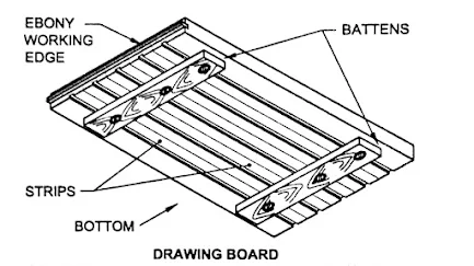
The drawing Board is rectangular fit as a fiddle and is made of stripes of all-around prepared delicate wood around 25 mm and 15 mm. thick. It is cleated at the back by two battens to forestall twisting.


drawing-board


One of the edges of the board is utilized as the working edge, on which the T-square is made to slide. It should, hence, be perfectly straight. In certain boards, this edge is grooved all through its length, and an entirely straight Ebony edge is fitted inside this depression. This gives a valid and tougher guide for the T-square to slide on. 


SIZES OF DRAWING BOARDS ( B or D )


SIZES             (Width × Length × Thick)


B0 or D0            1000×1500×25( mm.)


B1 or D1              700×1000×25( mm.)


B2 or D2              500×700×15 ( mm.)


B3 or D3              350×500×15 ( mm.)


The drawing board is made in different sizes. Its choice relies on the size of the attractive paper to be utilized. The extent of planning phases suggested by the Bureau of Indian Standards (IS:1444-1989) are arranged. 


For use in schools and universities, the last two sizes of the drawing boards are more advantageous. Huge size sheets are utilized in drawing workplaces of designers and designing firms. 

The drawing board is put on the table before the understudy, with its working edge on his left side. It is more helpful if the table-top is inclining downwards towards the understudy. If such a table isn't accessible, the vital slant can be acquired by putting an appropriate square of wood under the far-off longer edge of the board.


2. T-Square


T-Square is comprised of hard-quality wood, celluloid, or plastic. It comprises two sections named the stock or head and the blade - consolidated at right-angle(90°) to one another by methods for screws and pins. One of the distant edges of the blade which is generally beveled, is used as the working edge of T-square. The stock is set bordering the ebony edge of the board and is made to slide on it as and when required. The blade lies on the surface of the board. 

The working edge should be completely straight. The nearer edge of the blade is rarely utilized.


T-square with drawing board


The length of the blade is chosen to suit the size of the drawing board. The standard T-squares are as follows with dimensions shown in mm, as per IS:1360-1989.


SIZES OF T-SQUARES ( T )


SIZES                  ( Length of BLADE )


  T0                         1500 ( mm.)


  T1                         1000 ( mm.)


  T2                         700  ( mm.)


  T3                         500  ( mm.)


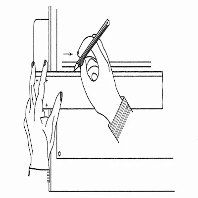
(i) The T-square is utilized for drawing horizontal lines. The stock or head of the T-square is held immovably or firmly with the left hand against the working edge of the board, furthermore, the line is drawn from left to right. The pencil ought to be held marginally slanted toward the direction of the line (for example to the right) while the pencil point ought to be as close as conceivable to the working edge of the blade. Horizontal parallel lines are drawn by sliding the stock to the required ideal positions.


T-square uses


ii) The working edge of the T-square is additionally utilized as a base for set squares to draw vertical, slanted, or commonly equal lines. A pencil must be pivoted while drawing lines for uniform wear of lead. T-square ought to never be utilized other than the ebony or working edge of the board. lt ought to consistently be kept on the board in any event, when not being used. 


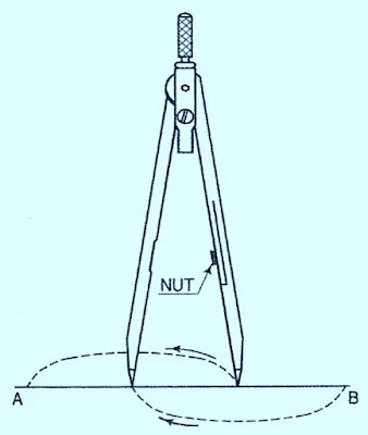
(iii) Testing the straightness of the working edge of the T-square: Mark any two points A and B divided wide separated and through them, cautiously draw a line with the working edge. Now, flip around the T-square as appeared by ran lines and with a similar edge, draw a different line going through the same two points. On the off chance that the edge is defective, the lines won't coincide. 

The mistake ought to be corrected by planning or sand-papering the defective edge.


3. Drawing Sheets


Drawing sheets or papers are two types : 

(i) Hand-made sheets or papers
(ii) Mill-made sheets or papers 

Hand-made sheets or papers :

These sheets or papers are pale in color, have rough surfaces, and are not used for regular work rather than used for making charts.

Mill made sheets or papers :

These sheets or papers are commonly used for most of the regular works and are available in different sizes & rolls. They are specified by their weight in kilogram per ream or density in grams per square meter.

Drawing sheets are accessible in numerous assortments. For conventional pencil drawings, the paper chosen ought to be extreme also, solid. It ought to be uniform in thickness and as white as could reasonably be expected. 

At the point when the eraser is utilized on it, its strands ought not to deteriorate. The great nature of paper with a smooth surface ought to be chosen for drawings that are to be inked and safeguarded for a long time. It ought to be with the end goal that the ink doesn't spread. Slender and modest quality paper might be utilized for drawings from which drawings are to be readied. Internationally drawing paper sizes are defined by ISO 216. However, paper sizes bigger than A0, i.e. 4A0 & 2A0, aren't formally defined by ISO 216 but are commonly used for oversized paper and defined by The DIN 476 oversize formats. The origin of these oversized formats is in the German DIN 476 standard. ISO 216 was actually derived from the base DIN 476. 2A0 is sometimes described as A00, but A0000 is not used for 4A0. In India, the standard sizes of drawing papers suggested by the Bureau of Indian Standards (B.I.S.) and designated as per IS:10811:1983.


PAPER OR SHEET SIZES FROM 4A0 TO A10


SIZES                          ( Width × Length )


4A0                               1682 x 2378 (mm)


2A0                               1189 x 1682 (mm)


A0                                   841 x 1189 (mm)


A1                                    594 x 841 (mm)


A2                                   420 x 594 (mm)


A3                                   297 x 420 (mm)


A4                                   210 x 297 (mm)


A5                                   148 x 210 (mm)


A6                                   105 x 148 (mm)


A7                                     74 x 105 (mm)


A8                                       52 x 74 (mm)


A9                                       37 x 52 (mm)


A10                                     26 x 37 (mm)


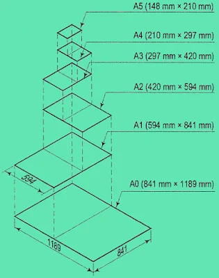
The surface region of A0 size is one square meter. Progressive arrangement sizes (from 4A0 to A10) are obtained by splitting along the length or multiplying along the width. The regions of the two subsequent sizes are in the proportion 1:2 as shown in the following figure.


drawing-sheet


Paper sizes from 4A0 to A3, are generally used for drawing where 4A0 to A0 papers are used in industries and A1 to A4 papers are used in schools & colleges. The A4 size has become the standard business letter size. A5 to A10 papers are used for books, notebooks, pocket notebooks, etc.


4. Drawing Sheet Container


Drawing sheet containers are comprised of hardwood, and bamboo, or in modern days it's made with heavy-duty plastics. It's also termed as a Chart holderChart containerDraft tubeDrafting tube, Drawing tube, etc.


drawing sheet container mechengineeringdrawing.blogspot


Drawing sheet containers, which are easily available in the market, are generally used for school and college students. It has an 8 c.m. internal diameter of the tube is 51 c.m. in length and extendable up to 80 c.m. or 31 inches. with a shoulder carrying strap which ensures extreme portability. It protects sheets from any external damage even from paper-worm bites and ensures a very long paper life.


5. Drawing Instrument Box

The following instruments should be in your instrument box. For keeping and carrying the drawing instruments safely, we can use a drawing instrument box, and you can buy this separately from the market. Thus there is no mandatory requirement to bring an instrument box except to keep your drawing instruments safer, but the drawing instruments are mostly required to start your drawing.

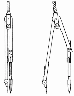
(i) Large-size engineering compass with inter-changeable pencil and pen legs : 

The compass is utilized for drawing circles and arcs. It comprises two legs pivoted together at its upper end. A sharp needle is fitted at the lower end of one leg, while a pencil lead is embedded toward the finish of the other leg. The lower part of the pencil leg is separable and it tends to be exchanged with a comparable piece containing an inking pen. Both the legs are furnished with knee joints. Circles up to around 150 mm radius can be drawn with the legs of the compass kept straight. For drawing bigger circles, both the legs should be bowed at the knee joints so they are perpendicular to the surface of the paper. 


Large compass - mechengineeringdrawing blogspot com


As the needle needs to be embedded somewhat inside the paper, it is kept longer than the lead point. The setting of the pencil-lead is compared with the needle, and what's more, the shape to which the lead should be ground. 


To draw a circle, adjust the opening of the legs of the compass to the required radius. Hold the compass with the thumb and the initial two fingers of the correct hand and spot the needlepoint gently in the middle, with the help of the left hand. Bring the pencil point down on the paper and swing the compass about the needle-leg with a spot of the thumb and the two fingers, in the clockwise direction, until the circle is finished. The compass ought to be kept marginally slanted toward the path of its revolution. while drawing concentric circles, starting ought to be made with the smallest circles.


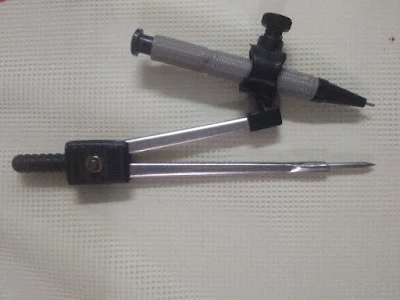
N.B: For school and college students, it is recommended to use a Self-centered or 0.5 m.m. compass which is also available in the marketplace. It is made with heavy-duty plastic so it's lighter in weight. In this compass, a push-back pencil comprised of 0.5 m.m. thickness lead, is readily fitted at the pencil insertion point. 


Self centered compass or 0.5 mm push back compass-mechengineeringdrawing.blogspot.com

Self centered compass or 0.5 mm push back compass-mechengineeringdrawing.blogspot.com


This push-back pencil can be easily detached from the compass and refilling new lead is too easy and it reduces the maintenance time ( like removal, sharpening, and fitting the pencil lead in ordinary compass ) which would be very helpful and time-consuming for the technical or engineering students during an examination. Circles with up to 135 m.m. radius can be drawn with this type of compass.


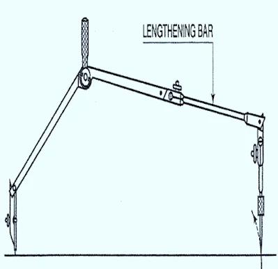
(ii) Lengthening bar :

In a large-size engineering compass,, the lower part of the pencil leg can be separated and the Lengthening Bar is embedded in its place. The Pencil leg is then fitted toward the finish of the lengthening bar, consequently expanding the length of the pencil leg. 


Lengthening bar - mechengineeringdrawing blogspot com


It is regularly important to control the pencil leg with the other hand while drawing enormous circles. Circles with more than 150 mm radius are drawn with the help of the lengthening bar, mostly used in industrial drawing.


(iii) Bow compass :


Small Bow Compass - mechengineeringdrawing blogspot com


For drawing little circles and curves of under 25 mm radius and especially, when countless little circles of the equivalent diameter need to be drawn, a small bow compass is utilized. This type of compass is smaller in size than ordinary compasses so sometimes it is termed a small-size compass.


(iv) Large-size divider :


The divider has two legs pivoted at the upper end and is given steel pins at both the legs on the lower ends, yet it doesn't have knee joints. 


Large size divider - mechengineeringdrawing blogspot com


The dividers are utilized for : 

(i) It is used to divide straight or curved lines into a desired number of equal parts.  


(ii) This can be used to transfer measurements from one part or portion to another part or portion of the drawing.


(iii) It is used to set off given dimensions from the scale to the drawing. 

Large dividers are extremely advantageous for setting off points at equal distances along a given line.


(v) Bow divider :


Bow divider - mechengineeringdrawing blogspot com


The bow divider is smaller in size than ordinary dividers, for this reason sometimes it's termed as a small divider. The bow divider is adjusted by a wheel nut and a spring. It is very helpful for marking very small divisions. It is also very convenient for a huge number of short equivalent separations.


(vi) Ruling pen or ink-pen :

The Ruling pen is a technical or engineering drawing instrument for drawing with ink or with other drawing fluids. This is utilized for drawing straight lines and non-circular arcs. It comprises a pair of steel nibs or jaws that are tapered to meet at a point and are approximately 11.8 c.m in length. It's very useful to draw very thin lines. The line width can be adjusted by an adjustment screw connecting the jaws. fitted to a holder made of metal or ivory. Ink is filled between the two nibs to about 6 mm internal diameter of a quill which is usually fitted with the cork or rubber. The ink flow line between the nibs through which the ink flows and upon which the thickness of the line depends is adjusted using the screw that optionally has an ink flow intensity controlling number dial.


Ruling pen or Ink pen - mechengineeringdrawing blogspot com

Ruling pens or Inking pen - mechengineeringdrawing blogspot com


The pen ought to be continued inclining at about 60° with the paper toward the direction of drawing and the finishes of the nibs ought to be marginally away from the edge of the T-square or set-square or scale.


(vii) Ruling pen attachment for compass :

Ruling pen attachments or Inking pen attachments are utilized for drawing circles and circular arcs, these ought to be fitted instead of the pencil leg in the compass.


Ruling pen attachment for compass - mechengineeringdrawing blogspot com


In the Ruling pen attachments, drawing ink or other drawing fluid dries rapidly, for this reason, the Ruling pen should be used immediately after it is filled with ink. The inside faces of the nibs should be frequently wiped out with a cleaned soft cotton cloth for the freely flowing ink and to maintain the uniform thickness of lines.


(viii) Technical pen :


Technical pen -2- mechengineeringdrawing blogspot com

Technical pen - mechengineeringdrawing blogspot com


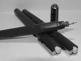
Technical pens are also very useful instruments used for engineering drawing, especially for electrical engineering drawing where various color indicators are also needed to draw for indication. However, it's frequently used in all types of engineering drawing industry.


6. Scales


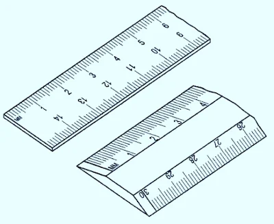
It is an instrument by which the length of an object or the shortest distance between two points can be measured. So, a scale is a length-measuring instrument. It is also used to transfer the true or relative dimensions of an object in the drawing.


There are generally five types of scale but three types of scale have huge applications or are mainly used in engineering graphics, those are :

(i) Plain Scale,

(ii) Diagonal Scale and 

(iii) Vernier Scale.

(Apart from the above, Comparative Scale & Scale of Chords are also classified as types of scale.)


In engineering drawing or technical drawing, Plain scale and Diagonal scale are mainly required and both types of scale also have a huge application in drawing. Vernier scale is mainly used in technical or engineering workshops.


Plain Scale - mechengineeringdrawing blogspot com


Diagonal Scale - mechengineeringdrawing blogspot com


Scales are made of wood, steel, celluloid, plastic, or cardboard. 15 cm long and 2 cm wide or 30 cm long and 3 cm wide level scales are in Common use. They are ordinarily around 1 mm thick. However, a 15 c.m. long and 2 c.m. wide scale is considered as the Standard length of the scale. 


Least count of Plain scale = 0.5 mm.

Least count of the Diagonal scale = 0.01 mm.

Least count of Vernier scale = 0.02 mm.


N.B.  Least count is a minimum distance or length that can be measured by a scale. ]

The scale should not be used as a straight edge for drawing lines to avoid the wear or damage of the edges.

For details about SCALE, you can learn it from here!


7. Protractor


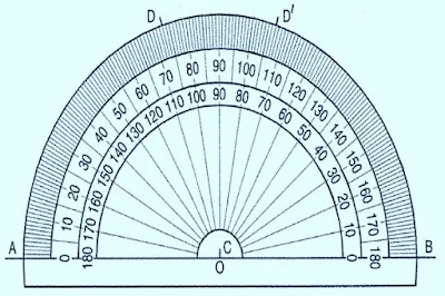
A protractor is an angle-measuring instrument used in technical drawing or engineering drawing. It is made of wood, tin, plastic, fiber, or celluloid. Nowadays, Protractors of transparent celluloid are common in use. Protractors are circular-flat or semi-circular-flat in shape. The commonest type of protractor is semi-circular and it's about 100 m.m. diameter. lts Circumferential edge is graduated with 1°divisions upto 180°, is numbered at every 10° interval. The diameter of the semi-circle (viz. straight line 0-180°) is called the base of the protractor and its center 'O' Is marked by a line perpendicular or 90° to it.


Protractor - mechengineeringdrawing blogspot com


The protractor is used to draw or measure such angles which cannot be drawn with set-squares. A circle can be divided into any number of equal parts using a protractor.


8.  Set-square


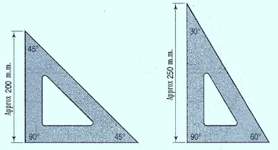
As per IS:1361-1988, the set-squares were made of wood or tin, etc. but nowadays, Set-squares are made of transparent celluloid or plastic as they retain their shape and accuracy for a very long time. There are two forms of set-squares for general use in engineering drawing. One is called 45° Set-square and another is termed as 30°-60° Set-square. A set-square is a flat triangular shape with one of its angles at a right angle(90°). Set squares may have smaller or larger sizes. Smaller size set squares can be found in the geometry box. A large size set-square is used for engineering drawing. larger 30°-60° set-square has a base of 145 mm ( approx 150 mm. ) and height of 245 mm ( approx 250 mm. ) whereas a 45° set-square has a base and height of 195 mm ( approx 200 mm ).


setsquare - mechengineeringdrawing blogspot com

(i) Set-squares are used for drawing all parallel straight lines except the horizontal lines which are usually drawn with the T-square more easily. Vertical lines can be drawn with the T-square and the set-square. However, horizontal lines, vertical lines, and parallel lines are also can be drawn with a set square by an expert hand (Not recommended for beginners) and it can omit the use of T-square.


(ii) Parallel straight lines in any position, not very far apart, as well as lines perpendicular to any line from any given point within or outside it, can also be drawn with the two set squares.


(iii) A circle can be divided into six, eight, twelve, and twenty-four equal parts by using set squares.


(iv) Lines at 30° or 60° angle with vertical or horizontal lines can be drawn with 30°- 60° set-square and 45° angle with 45° set-square. The two set-squares, used simultaneously, can produce angles of 15, 75°, 105° etc.


9.  French curves


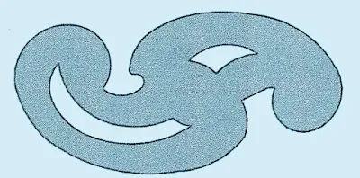
French curves are used to draw irregular curves which are generally unable to draw with a compass. The French curves were made of wood or tin etc. but nowadays, french curves are made of transparent celluloid or plastic as they retain their shape and accuracy for a very long time. The available sizes for the French curve are No.1 to No.18. but presently it's increased up to No.24.


french-curve.mechengineeringdrawing.blogspot.com


For Engineering Drawing, we generally use No.5 & No.6 in schools and colleges for educational purposes. Uses of French curves in Technical Drawing or Engineering drawing are a little tough and require some practice.


10.  Drawing Pencils


The quality of a drawing is highly dependent on the grade selection of the pencils used. With the wrong grade selection of pencils, it is very difficult to draw lines with uniform shade and proper thickness.

The grade of a pencil lead is usually shown by digits and letters marked at one of its ends. Letters HB ( Hard & Bold ) denotes the Medium grade. The increase in hardness is more useful to draw faint or thin-light lines and it is denoted by the value of the digit put in front of the letter H ('H' indicates Hard), viz. 2H, 3H, 4H etc. Similarly, the grade becomes softer according to the digit placed in front of the letter B ('B' indicates Bold), viz. 2B, 3B, 4B etc. A softer pencil is used to draw dark & thick lines.


pencil use for engineering drawing.mechengineeringdrawing.blogspot.com


For beginners, drawing should be made with HB or 2H pencil, so that the lines are faint, and unnecessary or extra lines can be easily erased. The final fair work may be done with softer pencils, i.e. 2B and upwards.


H and HB pencils are more suitable for dimensioning. For freehand sketching where considerable erasing is required to be done, medium-grade pencils such as HB should be used.


11. Pencil Lead Case or Box


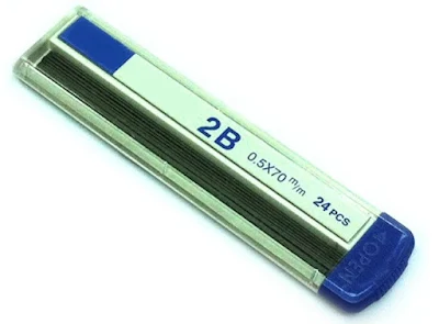
A pencil lead case or pencil lead box is used to keep pencil leads safe and it protects leads from breakage or any damage as pencil leads are made with soft polymer or graphite.

Pencil lead box or pencil lead case.image.mechengineeringdrawing.blogspot.com
Pencil lead box or pencil lead case..image1.mechengineeringdrawing.blogspot.com


A pencil lead case or box is easily available in the market. It is made up of celluloid or plastic.


12. Eraser (Rubber)


Eraser-rubber-mechengineeringdrawing.blogspot.com.jpg


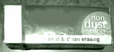
Eraser made up of rubber & easily available in the market for a very cheap price. It is used for unnecessary or extra lines that can be easily erased. But it should be used carefully such as not to damage the surface of the paper, so frequent use of erasers should be avoided by carefully planned drawing.


13. Erasing shield

Erasing shield is made of wood, a thin metallic sheet, or now in modern days, it is made of plastic or celluloid. It has small openings with different sizes and geometrical shapes. An opening is adjusted to the line or parts of the line which need to be erased and then the line is omitted by the eraser.


erasing shield image-mechengineeringdrawing.blogspot.com
Erasing Shield in Use


During drawing, sometimes a line among many other lines or a part of a line needs to be erased accurately, in general way of erasing, this may damage or omit other nearby lines. To overcome this critical situation an erasing shield is an excellent instrument.


14.  Sand-paper block or Pencil sharpener
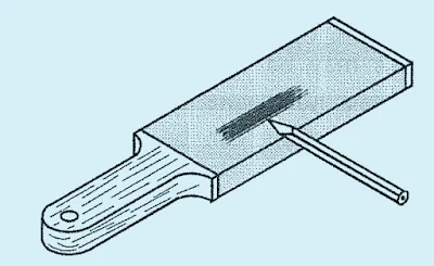

In modern days, the use of sand-paper blocks or sharpeners has been reduced during drawing to minimize maintenance time loss. However, previously, these had a wide application.


Sand-block-mechengineeringdrawing.blogspot.com.jpg
Sand Block

Pencil-Sharpener-machine-mechengineeringdrawing.blogspot.com.jpg
Pencil Sharpener Machine


It consists of a wooden block about 150 mm in length, 50 mm in breadth, and 12 mm thick with a piece of sand-paper pasted or nailed on about half of its length. The sandpaper should be replaced by another piece when it becomes dirty or worn out. This block should always be kept within easy reach for sharpening the pencil lead every few minutes.


15. Drawing pins, clips, or adhesive tapes
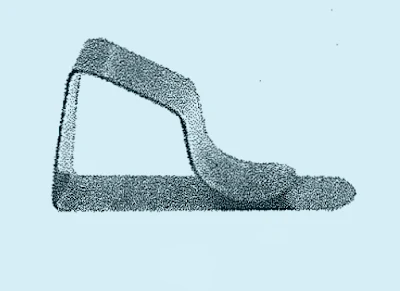

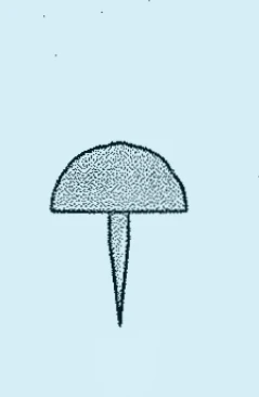
These instruments are used to fix the drawing paper on the drawing board. Board pins have snap or flat heads of about 10 mm to 20 mm in diameter and about 1 mm thick, made of plastic, mild steel, or brass are quite convenient, as they do not get rust. The needle part of the pin is generally made of steel. Pins should be so inserted that the heads sit on the surface of the paper.


Board-clips-mechengineeringdrawing.blogspot.com.jpg
Board Clips

Board-pins-mechengineeringdrawing.blogspot.com.jpg
Board Pins

Adhesive-tape-mechengineeringdrawing.blogspot.com.jpg
Adhesive Tape


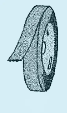
In modern days, board clips are widely used as it doesn't damage the drawing sheets. Board clips are also made of mild steel, brass, plastic, or celluloid. Adhesive tapes are often used instead of board clips or board pins.


16. Duster


The duster should be preferably a small piece of towel or cotton cloth of convenient size. Before starting drawing, all the instruments and equipment should be thoroughly wiped with the duster. The rubber crumbs formed after the use of the eraser should be swept away by the duster and used not by hand. The underside of the T-square and the set-squares or the drafting machine which continuously rubs against the paper should be frequently cleaned again and again during drawing.


17. Roll-n-draw


Roll-n-draw-image-mechengineeringdrawing.com


As it's named after, this consists of a roller as a handle on one of its sides for providing a compact grip on this instrument during drawing. There is a scale of 16 centimeters long and a 180° or semi-circular protractor is fixed to another side of this instrument. it is ideal for drawing vertical lines, horizontal lines, parallel lines, and angles. It is made of celluloid or plastic.


18. Drafting machine


Drafter or drafting machine.mechengineeringdrawing.blogspot.com


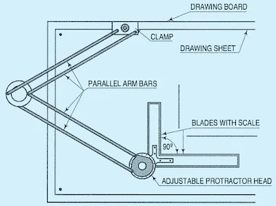
In a Drafting machine, one end is clamped using a screw with the distant longer edge of the drawing board. At its other end, an adjustable threaded head having protractor markings is fitted. Two blades of transparent celluloid accurately set at right angles to each other are attached to the adjustable head so that they can be set to any angle as required. The uses and advantages of the drafting machine are, that it is a total combination of T-square, set-squares, scale, and the protractor. So, the invention of a drafting machine reduced the use of many major instruments used for engineering drawing or engineering graphics. It also reduces the time losses for handling instruments separately & repeatedly during drawing.


Though there are a lot of instruments named in the list yet below is the list of minimum drawing instruments that every student must possess to start a drawing initially:

1. Drawing Board (if drawing is used to be done on a drawing sheet only).

2. T-square (if drawing is used to be done on a drawing sheet only).

3. Drawing papers or Drawing sheets or Drawing Exercise notebook.

4. Large-size compass or 0.5 mm self-centered push-back compass.

5. Large-size divider.

6. Scales (Plain scale and Diagonal scale).

7. Protractor (Circular or semi-circular).

8.  Set-squares- 45° and 30°- 60°.

9.  French curves ( No. 5 and No. 6 ).

10. Drawing pencils (0.5 mm pencil or Pushback pencil).

11. Eraser (Rubber).

12. Drawing clips or Board clips (if drawing is used to be done on a drawing sheet only).

Marked Valuable Posts!

IMPORTANT SHORT QUESTIONS AND ITS ANSWERS FROM ENGINEERING DRAWING INSTRUMENTS

  ●  Fill in the blanks type Questions :   1.  The full form of BIS is ……………………… Ans:  Bureau of Indian Standard. 2.  The inclination of inclined lettering as per BIS is ……………………. Ans:  75° 3.  Set squares are used for drawing ……………………. lines. Ans:  Parallel [ Vertical, Horizontal, Inclined ]. 4.  Angle of multiple of as constructed by the combined use of …………… & ………….. Ans:  T-SQUARE & SETS SQUARE. 5.  In the absence of protractor, ………………………. Is used to measure angles. Ans:  Angle of Chords. 6.  The scale of chords is used to measure ……………………….. Ans:  Angles. 7.  Two methods/systems to represent the dimensions are …………………. and …………….. system.  Ans:  Aligned and Unidirectional. 8.  Lettering is usually done in ……………….. letters. Ans:  Capital. 9.  The size of the letter is described by its ………………………….  Ans:  Height. 10.  Single stroke letters may be either …………………… or ………………………… Ans:  Vertical or Inclined. 11.  The dimension line should not ………………………. each other. Ans:  Cross / I

LAYOUT OF BORDERS AND TITLE BLOCK ON DRAWING SHEET

Post Summarization: ● Introduction. ● Size of drawing sheets. ● Margin. ● Borderlines. ● Title block. ● Rules for selecting Titles. ● Revision Table. ● Notes. ● Tutorial Videos (Coming Soon!) INTRODUCTION: A drawing sheet consists of an engineering drawing and must have some other aspects too i.e. Border lines, Title block, Notes, etc for better demonstration of the drawing. The layout of border lines and title blocks should always be done in some specific manner on the drawing sheet as it's not only a necessity for increasing the visual orientation of the drawing sheets, moreover, these help to read the drawing sheet more speedily in a systematic way. SIZE OF THE DRAWING SHEET: The size of the drawing sheet in detail can be found in the  TECHNICAL DRAWING AND INSTRUMENTS of this blog. MARGIN: Margin or Marginal lines are drawn on the drawing sheet only where the untrimmed size of the drawing sheet is provided. Generally, in the paper industry, trimmers are used to trim drawing sh

IMPORTANT SHORT QUESTIONS & ITS ANSWERS ON CURVE & LOCI

IMPORTANT SHORT QUESTIONS : 1.  A locus is the path of a point which moves in ……………………… Ans:  Same plane. 2.  When the section plane is inclined to the axis and is parallel to one of the generators, the section is a ………………… Ans:  Parabola. 3.  When the section plane is inclined to the axis and cuts all the generators, on one side of the apex, the section is an ……………….. Ans:  Ellipse. 4.  When the section plane cuts both the parts of the double cone on one side of the axis, the section is ……………. Ans:  Hyperbola. 5.  If eccentricity (e) of a curve is equal to 1, the curve is said to be ………………. Ans:  Parabola. 6.  If eccentricity (e) of a curve is less than 1, the curve is said to be ………………. Ans:  Ellipse. 7.  If eccentricity (e) of a curve is greater than 1, the curve is said to be …………. Ans:  Hyperbola. 8.  The ………… is the point at which the conic cuts the axis. Ans:  Apex / Vertex. 9.  The ………….. is the point at which the generator cuts the axis. Ans:  Apex / Vertex. 10.  The point at

LETTERING

 LETTERING: INTRODUCTION Writing titles on drawing sheets, dimensions on drawing objects, special notes, and other important particulars on a drawing is called Lettering. It is a very important step in an engineering drawing. Lettering should, therefore, be done properly in a clear, legible, and uniform style. It should be in plain and simple style so that it could be done freehand and speedily. Any ornamental style must be avoided lettering in engineering drawings. Though accurate and neat drawings may be drawn yet sometimes, their appearance is spoiled by ornamental lettering or sometimes, their usefulness is decreased by poor lettering.   Note:  The use of drawing instruments in lettering takes considerable time and hence, it should be avoided to save time, especially in the examination hall. Efficiency in the art of lettering can be achieved by careful and continuous practices. **Actually, a free hand drawing means, "keeping almost the same visual shape, you can draw any comp

IMPORTANT! Short Questions and Answers from SCALE

  IMPORTANT SHORT QUESTIONS AND ANSWERS FROM SCALE 1. An instrument used to measure the length or distance between two objects or points, termed as.................. Ans: Scale. 2. The scale of chords is used to measure ……………………….. Ans: Angles. 3. The ratio of drawing length to the actual length of an object is called ………………………. Ans:   Representative Fraction. 4. When measurements are required in two units or a unit and its subdivision, the ………………… is used. Ans:   Plain scale. 5. When measurements are required in three units, the …………………. Scale is used. Ans:   Diagonal. 6. When a drawing is drawn of the same size as that of the object, the scale used is …………………. Ans: Full-size  scale   7. When drawings are drawn smaller than the actual size of the object, the scale is said to be ………….. Ans:   Reducing scale 8.   R.F. is the ratio of .................................. to the .................................. Ans: Drawing Length of an object, Actual Length of that object. 9.

INTRODUCTION OF ENGINEERING DRAWING

INTRODUCTION OF ENGINEERING DRAWING Simply you can say, it is a special type of language globally used for engineers or technical persons to communicate between them for fulfillment of target or making any geometrical shaped object or rather say any project. Suppose, there is a building or bridge construction or maybe the construction of an electric or power substation, or maybe in a mechanical workshop, we need various types of technical persons or specialists for construction or production. As an example, some engineers ensure the stability of load capacity of the ground and how much load can bear that ground by doing the field survey, some technical persons or engineers develop the structure or construction, and some technical person completes the fabrication ( i.e. riveting or welding ) portions, some technical persons or engineers develop the electrical supply connections and so on. All technical persons and engineers come together to complete a project or projects but they all n

SCALE

INTRODUCTION TO SCALE :   Scales are made of wood, steel, celluloid plastic, or cardboard. 15 cm long and 2 cm wide or 30 cm long and 3 cm wide level scales are in Common use. They are ordinarily around 1 mm thick. However, a  15 c.m. long and 2 c.m. wide scale is considered a Standard length of scale.  By using scale, small components can be drawn with the same size as the components are actually. A 150 mm long pen or 175 mm long pencil may be shown by a drawing of 150 mm length or 175 mm length respectively. Drawings of the same size as the objects are called full-size drawings and ordinary full-size scales are generally used to draw such drawings. A scale is determined by the ratio of the dimensions of an element as represented in a drawing to the actual dimensions of the same element. This is called R.F. or Representative Fraction of Scale. The scales are generally classified as : (1) Plain scales (2) Diagonal scales (3) Vernier scales (4) Comparative scales (5) Scale of chor